A newly published patent details the Switch 2 magnetic connector. It’s dense so I’ll give only an overview here. Click this link to read the patent in full.
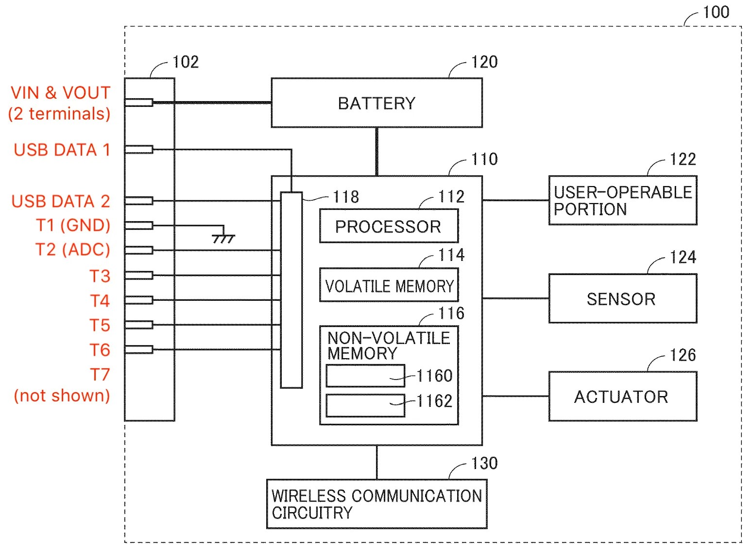
- The connector supports I2C, UART, SPI, and USB communications.
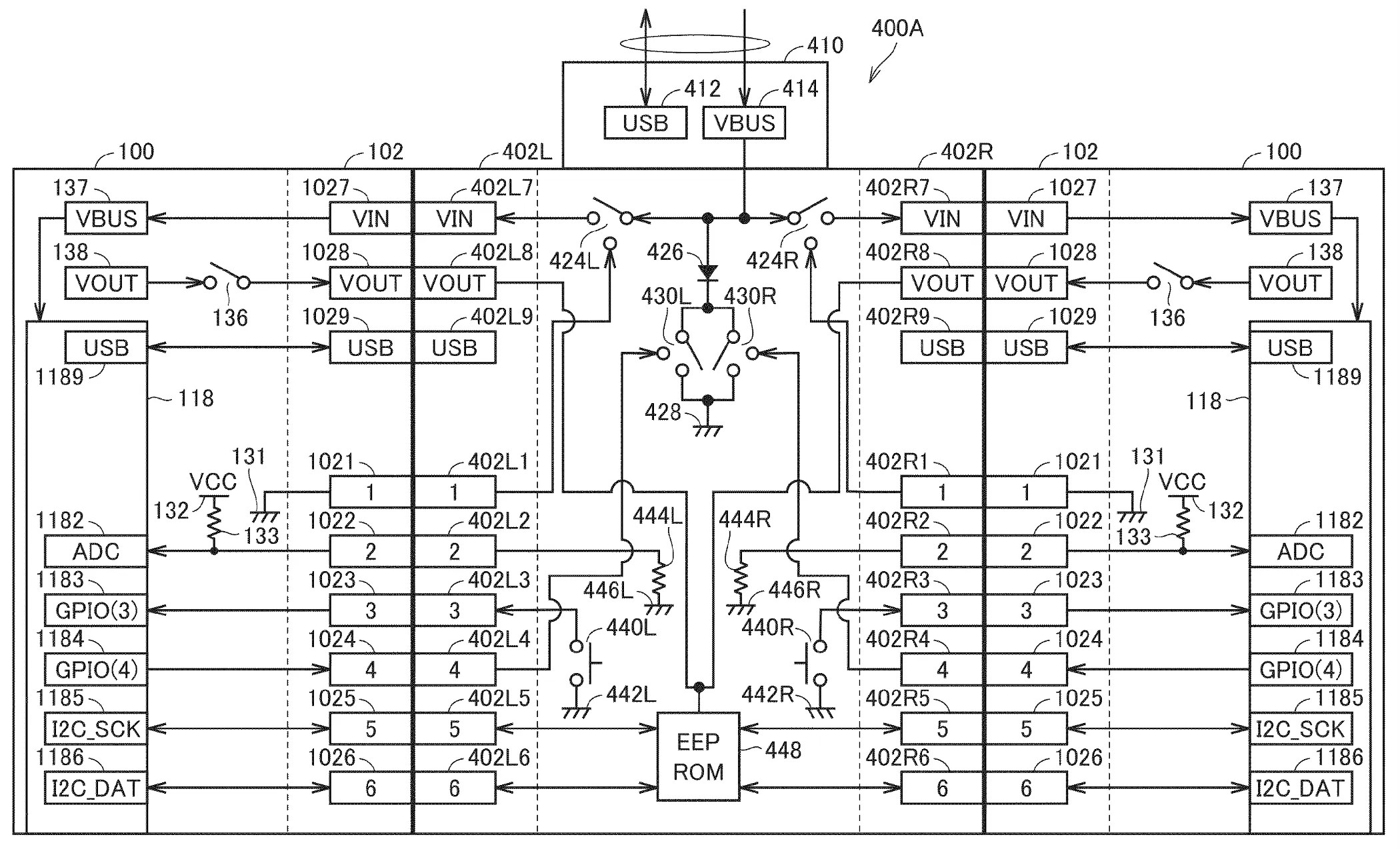
- USB is always available; I2C, UART, and SPI share T3-T6 (img below shows the controller side).
- Joy-Con’s T2 detects a connected resistor behind the console’s or accessory’s T2. The resistor value determines the comm mode—I2C, UART, or SPI.
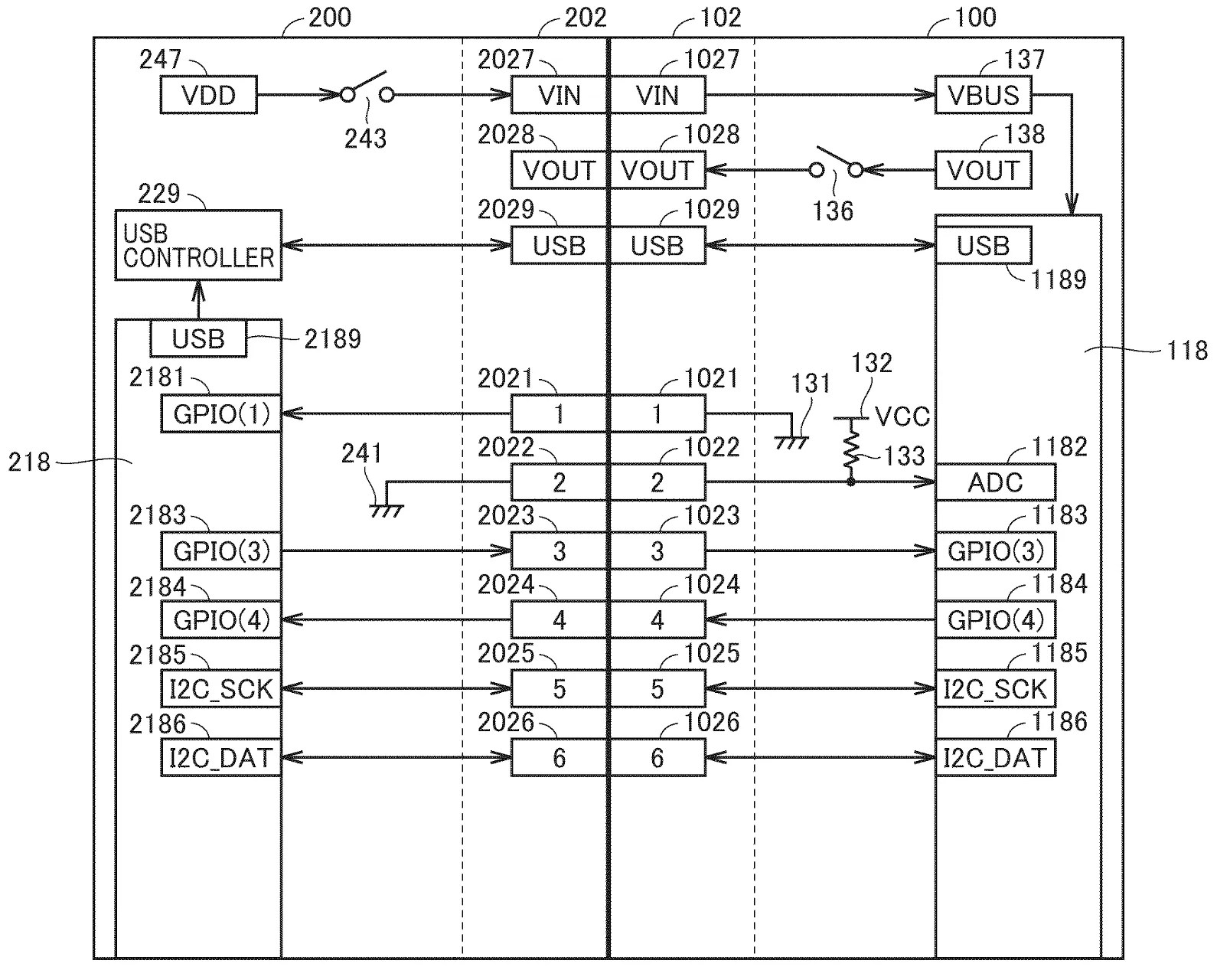
- When a Joy-Con is attached to a console (img below), I2C is used for the initial handshake (e.g., identifying the controller color) before switching to USB.
- In I2C mode: T3=comm-request, T4=comm-ready, T5=SCL, T6=SDA
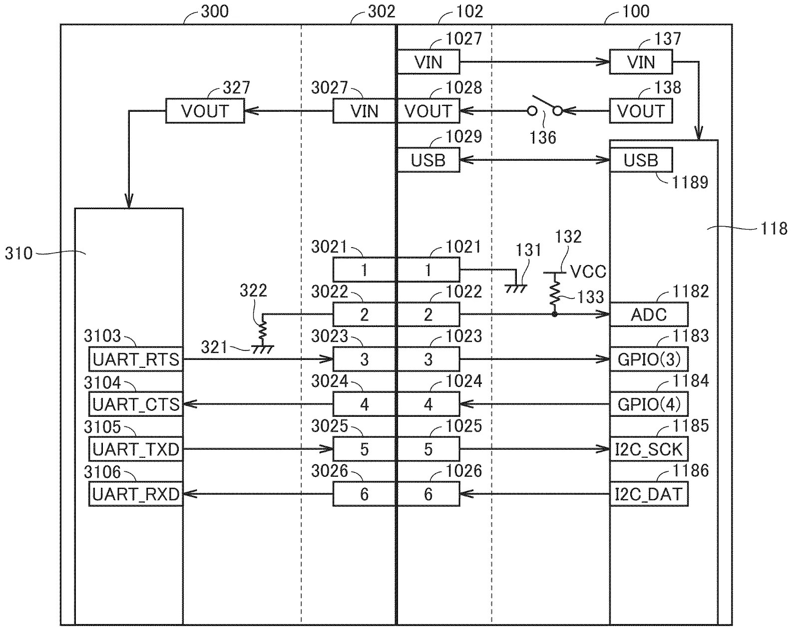
- When a Joy-Con is attached to a UART accessory such as the Ring Con (just an example; img 1 below): T3=RTS, T4=CTS, T5=TX, T6=RX
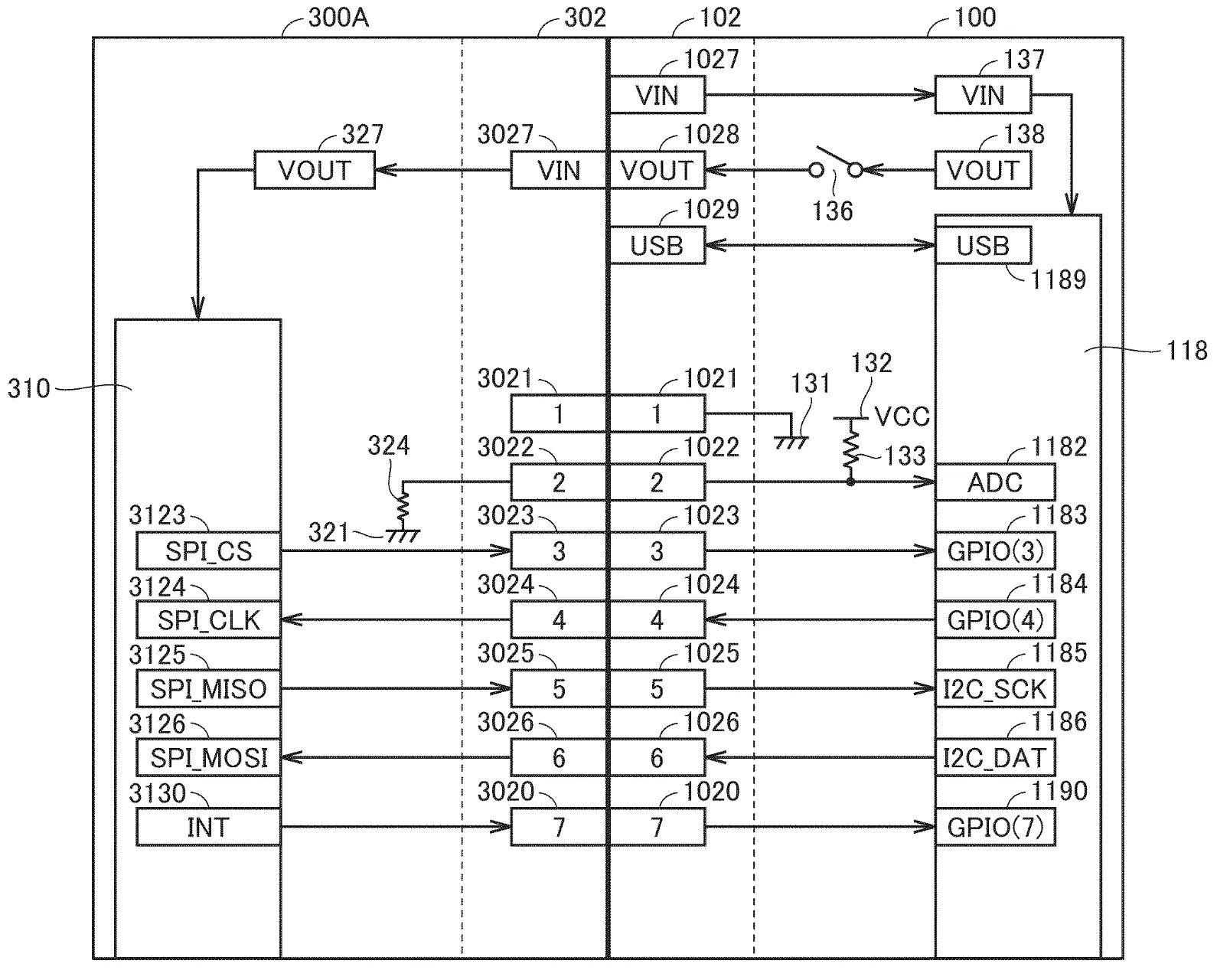
- With an SPI accessory (img 2): T3=CS, T4=CLK, T5=MISO, T6=MOSI, T7=INT
- The T7 in SPI mode is optional, for receiving interrupt signals. (This may be useful for a motion-sensing type of accessory, such as a new Ring Con.)
- A certain resistor value is reserved for the Joy-Con 2 Charging Grip. In this mode, T3 is for GL/GR button, and T4 for charging LED (img below).
Note that the actual magnetic connector contains 13 terminals, but the patent shows only 11. Since the Joy-Con can be attached upside-down, I think that the 2 extra pins are redundant.
[Originally posted on 2026-07-16 Pacific Time]
